Repariable Systems
FaultTree User's Tutorial
TOCRepairable System Models
Following the initial successes of fault tree analysis in the aerospace arena through the 1960's, the Rasmussen report of the mid-1970's launced the U.S. nuclear industry's embrace of fault tree analysis and probabilistic risk assessment. Concern that loss of reactor core cooling leading to a loss of containment "China syndrome" caught the public attention. As historical backdrop one should recall that manned flight to the moon first occurred in 1969, while the oil embargo of 1973 lead to a major expansion in the construction of nuclear power generation. Additionally, the 1974 Flixborough incident in England placed new emphasis on process safety in the chemical, oil and gas industries including use of fault tree analysis.
This expanded use of fault tree techniques introduced a new aspect in that the repair or replacement of failed components was expected to maintain a continuous operation. In this realm the probability of failure over a mission (unreliability) is replaced by probability of a failed state over time (unavailability), while frequency of failure becomes the focus of most "top" undesired events. In this model, repair time becomes a required input in addition to fail rate for characterization of components.
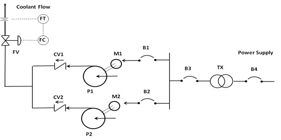
To introduce this topic consider a hypothetical coolant pumping scenario. The undesired event in this example is loss of adequate coolant flow. Such a loss to an exothermic process whether chemical or nuclear can lead to significant safety concern. The coolant is propelled by a pair of centrifugal pumps provided in a shared load array for redundancy. Adequate cooling flow can be provided as long as a one of the two pumps is in operation. A flow control valve on the combined discharge of the pumps back-pressures the pumps causing them to "walk up" the pump curve to reduce coolant flow to a normal rate as both pumps run continuously. This control saves power and reduces wear on downstream components. Check valves on the discharge of each pump prevent flow from recycling backwards through a non-operating pump.
Both pumps are electric motor driven. The power supply is conditioned by a transformer and controlled by several breakers.
The following table summarizes the input parameters:
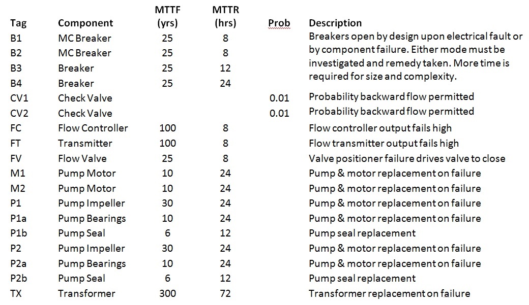
These are fairly realistic values for failure. Repair times reflect assumptions regarding availability of replacement components, parts, and repair personnel.
A fault tree for this system is constructed, calculated, and viewed by the following script:
cool<-ftree.make(type="or", name="Coolant Flow", name2="Insufficient")
cool<-addLogic(cool, at= 1, type="and", name="Pumps Fail", name2="Independently")
cool<-addLogic(cool, at=1, type="or", name="Common Cause", name2="Pumping Failure")
cool<-addLogic(cool, at=2, type="or", name="Pump 1", name2="Failure")
cool<-addActive(cool, at=4, mttf=30, mttr=24/8760, tag="P1", name="Pump Impeller", name2="Fails")
cool<-addActive(cool, at=4, mttf=10, mttr=24/8760, tag="P1a", display_under=5,
name="Pump Bearings", name2="Fail")
cool<-addActive(cool, at=4, mttf=6, mttr=12/8760, tag="P1b", display_under=6,
name="Pump Seal", name2="Fails")
cool<-addActive(cool, at=4, mttf=10, mttr=24/8760, tag="M1", display_under=7,
name="Pump Motor", name2="Fails")
cool<-addActive(cool, at=4, mttf=25, mttr=8/8760, tag="B1", display_under=8,
name="Pump Motor Control", name2="Breaker Opens")
cool<-addLogic(cool, at=2, type="or", name="Pump 2", name2="Failure")
cool<-addActive(cool, at=10, mttf=30, mttr=24/8760, tag="P2",
name="Pump Impeller", name2="Fails")
cool<-addActive(cool, at=10, mttf=10, mttr=24/8760, tag="P2a", display_under=11,
name="Pump Bearings", name2="Fail")
cool<-addActive(cool, at=10, mttf=6, mttr=12/8760, tag="P2b", display_under=12,
name="Pump Seal", name2="Fails")
cool<-addActive(cool, at=10, mttf=10, mttr=24/8760, tag="M2", display_under=13,
name="Pump Motor", name2="Fails")
cool<-addActive(cool, at=10, mttf=25, mttr=8/8760, tag="B2", display_under=14,
name="Pump Motor Control", name2="Breaker Opens")
cool<-addLogic(cool, at=3, type="or", name="Flow Control", name2="Restricts Flow")
cool<-addActive(cool, at=16, mttf=25, mttr=8/8760, tag="FV", name="Flow Valve Closed",
name2="By Positioner")
cool<-addActive(cool, at=16, mttf=100, mttr=8/8760, tag="FC", display_under=17,
name="Flow Valve Closed", name2="By Flow Controller")
cool<-addActive(cool, at=16, mttf=100, mttr=8/8760, tag="FT", display_under=18,
name="Flow Valve Closed", name2="By Flow Transmitter")
cool<-addLogic(cool, at=3, type="or", name="Flow Recycles Through", name2="Failed Check Valve")
cool<-addLogic(cool, at=20, type="inhibit", name="Pump 1 Stops", name2="with CV1 Failed")
cool<-addProbability(cool, at=21, prob= .01, tag="CV1",
name="Check Valve", name2="Fails on Demand")
cool<-addDuplicate(cool, at=21, dup_id=4)
cool<-addLogic(cool, at=20, type="inhibit", name="Pump 2 Stops", name2="with CV2 Failed")
cool<-addProbability(cool, at=29, prob= .01, tag="CV2",
name="Check Valve", name2="Fails on Demand")
cool<-addDuplicate(cool, at=29, dup_id=10)
cool<-addLogic(cool, at=3, type="or", name="Power Interrupted", name2="To all Pumps")
cool<-addActive(cool, at=37, mttf=25, mttr=12/8760, tag="B3", name="MCC Breaker", name2="Opens")
cool<-addActive(cool, at=37, mttf=25, mttr=12/8760, tag="B4", display_under=38,
name="Transformer Breaker", name2="Opens")
cool<-addActive(cool, at=37, mttf=300, mttr=72/8760, tag="TX", display_under=39, name="Transformer", name2="Fails")
cool<-ftree.calc(cool)
ftree2html(cool, write_file=TRUE)
browseURL("cool.html")
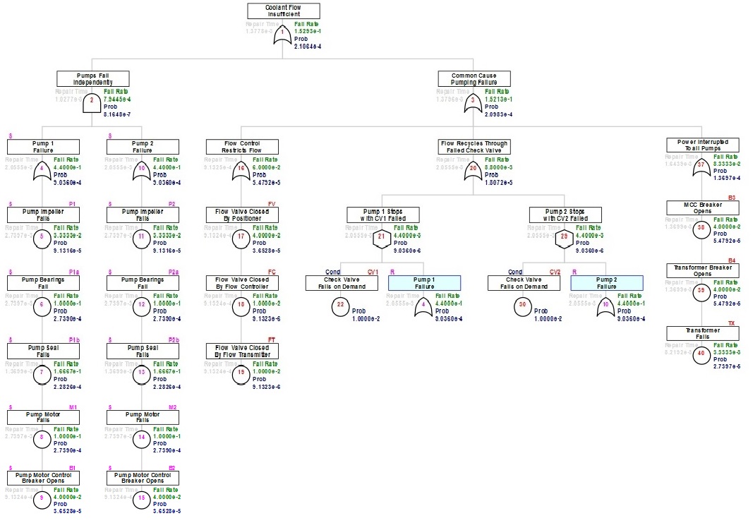
This script utilizes the addActive function to define basic events. Active components are typically found to be operating. However the true determinant is that failures of active components will be realized immediately. Since this is a repairable model, both mttf and mttr values are required to define an active component. The display_under argument has been used in some instances. This argument simply permits the graphic display of sibling basic events to display in a vertical chain-like fashion under an OR gate. When this argument is set, checks are made to verify common parentage under an OR gate and then modification is made to the GParent field of the component row in the dataframe. In this case a wide display of 5 children under each appearance of the OR gate defining single pump failure would have been difficult to view if placed horizontally.
Each of the check valves on pump discharge were modeled as a condition having a failed state probability. These check valves would not pass the active component definition, because it is not possible to tell that such a check valve may have been corrupted during normal system operation.
The unavailability of each active component is calculated according to mttr/(mttf+mttr). This is the probability that the component is in a failed state over time. The fail rate, appearing in the graphic for each active component is 1/mttf. All time units must be maintained consistent on input. In this case years were chosen such that hours of repair time must be input as hours/8760 so that the repair time is represented as the fraction of a year.
In the OR gates the output probability is the result of a probabilistic sum from the input events, identical to the calculation under the non-repairable model. The combined fail rate is the direct sum of input fail rates. The repair time is calculated based on combined fail rate and active component unavailability to represent a mean repair time.
At the INHIBIT gates, the fail rate and unavailability of individual pump failure as combined in the duplicated OR gate are multiplied by the probability of a failed check valve. If only 1% of the time a check valve is in a failed state, then only 1% of the times that the single pump fails will result in the recycle failure. An assumption is applied that the repair time for a single pump failure is unchanged, therefore the resultant unavailability after the inhibit calculation is the product of the condition probability and the feeding node unavailability.
The AND gate calculation is similar to two INHIBIT gates combined by an OR. Independent dual failure occurs under the condition that one component is in a failed state when the other fails. Two inhibit gates combined this way would be slightly inaccurate due to double counting of the times when both are down. The actual 'cross-product' calculation for fail rates at the AND gate is performed by the following formula: fail_rate1 * prob2 + fail_rate2 * prob1 - (fail_rate1+fail_rate2) * prob1 *prob2. Unavailability probabilities are combined in the AND as a product of input probabilities, identical to the calculation under the non-repairable model. The repair time after AND combination is then calculated based on the combined fail rate and active component unavailability values similar to the OR gate.
It is a recommended student exercise to perform a check of the gate calculations for this example in a spreadsheet to confirm understanding of these processes.
In this example the flow control loop places a significant burden on the success of adequate cooling. It is not uncommon to find features placed in a design for safety, energy efficiency, or even presumed reliability enhancement that impact the undesired event adversely. It can be more effective in cases such as this for the fault tree analyst not to attempt elimination of the feature (which is sure to encounter resistance), but to identify recommendations that can enhance the system with them in place. The flow control loop in this example is contributing no more than half of the quantified fail rate for the top event. Simply having both pumps driven by electric motor is of equivalent importance. Typically if order of magnitude improvement is required, features such as steam and/or diesel powered pumps in a secondary cooling system might be considered. Although not examined in this example, a diversity in the source of coolant might be justified as a secondary backup.
The primary focus on importance is the contribution to the fail rate in OR gates immediately under the top event. The probability values, unavailability, is of lesser importance until failure of this system is considered a condition for combination with other protections.
TOC
NEXT -->